Poster
Client Context
The Robins Air Force Base (RAFB) is in Warner Robins, Georgia. RAFB is home to the largest military installation in Georgia and is responsible for the maintenance/repair of the United States Air Force’s aircraft and weapon systems. This project is specifically for the 574th Structural Repair Squadron.
The 574th Squadron maintains 33 different part types for C-5, C-17, C-130, and F-15 aircraft and operates across five buildings. Four buildings (169, 189, 180, 323) are located at the main base, and the fifth (Robins North) is located five miles north of the main base.
Parts follow a sequence of gates to complete their repair process. Each part has a primary workshop in building 169 or Robins North, where specific equipment for that part type’s repair process is located. A workshop is generally broken up into several gates. Most parts also travel to multiple backshops located in buildings outside of a part’s workshop and house processes used for many part types.
Project Objective
The client’s main problem is the excess flowdays (FDs) used to complete a part’s repair process. A FD is a 24-hour period the client uses to measure cycle time. The client’s goal is to return repaired Air Force aircraft to the field as soon as possible. The current system has inefficiencies regarding queue times and transport times that can be improved to help the client achieve their goal.
The main issue causing increased cycle times is excessive queue times at backshops. The client mentioned backshops as a primary bottleneck; however, they do not track queue times specifically and therefore the team decided to utilize the validated simulation to check this assumption. In the 574th squadron, 26 parts’ repair processes use the depaint backshop and 28 use the paint backshop. All 13 backshops used by the 574th squadron, including paint and depaint, are shared with two other squadrons. The paint shop alone processes roughly 1,300 individual parts annually from other squadrons. By analyzing the current system simulation (validated by the client), the team discovered that the three most significant backshop bottlenecks are the X-Ray NDI (non-destructive inspection) backshop in building 323 and paint and depaint backshops in building 180. The current simulation queue times for X-Ray NDI, paint, and depaint are 2.86, 2.2, and .25 FDs, respectively. X-Ray NDI and paint observe the longest queues, with the paint queue equating to roughly 7.5% of the average cycle time of all parts in this system. Increasing the capacity of the X-Ray NDI would require the construction of a new machine, which is too expensive for the client. Therefore, the focus to reduce queue times is on the paint and depaint backshops.
Another inefficiency is that parts are transported to backshops outside of their building several times. For example, C-5 flaps travel to buildings 169 à 180 à 323 à 169 à 180 à 169 to complete their entire repair process for a total of five movements between buildings. Parts spend an estimated 0.5 FDs for inter-building travel on base and 1 FD for inter-building travel off-base, leading to C-5 flaps spending 2.5 flowdays on travel alone. These five trips also increase the probability of misplacing or temporarily losing a part. When parts are transported multiple times, they are sometimes forgotten in certain locations, leading to lost process time and additional labor time spent searching for the part.
Additionally, the current system is inadequately prepared to handle the client’s projected 20% demand surges during months with increased demand. These surges will increase the average time in system for each part due to longer queues at backshops, which will decrease the client’s ability to achieve their goal of quickly returning parts to the field.
To address this problem, the client has specified a plot of land on the main base for a proposed new facility/building. The project aims to consolidate workshops and backshops by designing a layout that reduces cycle times by decreasing queue and travel FDs.
Design Strategy
The design decision variables in the project are the workshop/backshop location (moved to the new building or unchanged location) and placement within the new building if moved. Moving a backshop to the new building would require buying new equipment for that backshop; if a workshop is moved, all its machinery relocates to the new building.
The client requires the following categories of constraints for the new layouts: fixed equipment – some buildings have fixed equipment that cannot be moved or is too expensive to move; Resource Cost Center (RCC) grouping – RCCs group workshops that share similar machinery, so they must stay together; new building dimensions – the client currently has 193,500 sq. ft. allocated for this project; off-base travel elimination – the client wants to remove all their workshops from Robins North to eliminate off-base travel.
The client also has a set of preferences to acknowledge when designing the new building layout: paint and depaint adjacency, non-disruptive location of paint and depaint, and argus placement. The paint and depaint backshops use similar equipment, emit potentially harmful fumes, and require a wall around them. They would ideally be placed next to each other and in the corner, away from other processes; however, the client is interested in seeing potential tradeoffs between layouts and FDs that could make an alternative placement worth the extra construction. The argus backshop is a type of NDI equipment that is expensive to purchase or move, but the client would like insight into its potential benefit in the new building to decide if it is worth the cost.
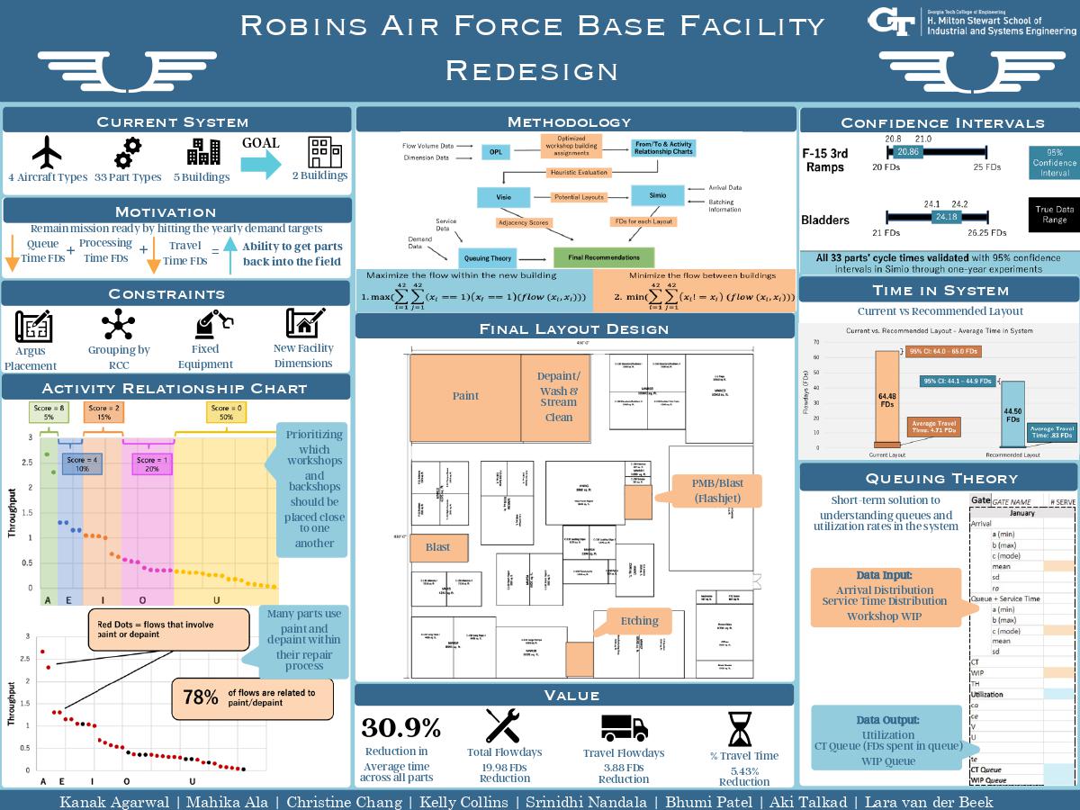
As seen in the figure below, there are five main methodologies for solving the client's problem: OPL, From/To & Activity Relationship Charts, Visio, Simio, and Queuing Theory.
Deliverables
The final deliverables are a recommended building layout in Visio, a simulation metrics analysis, and the queuing interactive spreadsheet.
The final layout, shown above, has paint and depaint together in the corner of the building and does not include argus equipment, which are the two distinguishing factors from the other generated alternatives. The steps for this analysis considering simulation output and client preferences are described in section 4.5 of this report. This layout also considers aisles that must be at least 14 feet wide and work-space amenities, including bathrooms, offices, consumables storage, and break rooms. This layout is a Visio file that can be converted into a pdf for convenience or into an AutoCAD file, which is the client’s file type for their current layouts.
In addition to the recommended layout, the team analyzed the benefits of this layout compared to the client’s current layout based on the output from the simulation experiments. The client will receive an Excel spreadsheet with this analysis. It shows the flowday and throughput comparisons for each layout, including the current system, the current system with 20% increased demand, and the six alternatives. The spreadsheet also includes in-depth cycle time, backshop queue time, throughput data, and a key to specify different terms. The client can use this data to compare the different layout alternatives and justify the improvements this project can bring to the 574th squadron regarding decreasing FDs and increasing throughput.
The interactive queuing spreadsheet is a short-term deliverable solution for the squadron to adjust their system until they receive funding for the new building. The spreadsheet indicates where to input interarrival distribution, service time distribution, and workshop WIP data. It automatically computes utilization, cycle time queue, and WIP queue. Furthermore, it displays graphical representations of cycle time and WIP queues for gates in the whole system and for each part. These visuals will make it easier to pinpoint the exact gates that require additional capacity.
Value and Impact
This project’s primary goal was to decrease the cycle time, measured in FDs, for each part type’s repair process. This decrease was measured in two primary ways: travel and queue time. The team found that most of the travel time overlapped with queue time, so when parts arrived after being transported, they still had to wait in a queue to be serviced. Therefore, the goal of decreasing travel time is mainly for benefits outside of cycle time, such as reducing travel costs, system complexity, and mismanagement of parts. The cost and labor going towards transport can be invested in the system repair processes instead, and the chance of parts being lost in different locations is reduced. The decrease in cycle time is mainly affected by a reduction in queue time, which is directly related to installing new backshops that are reserved for only the 574th Squadron. The primary bottlenecks in this system are repair gates and backshops. Since paint and depaint are utilized by almost every part type in the 574th Squadron, in addition to parts from two other squadrons, they became the highest priority to add to the new layout. By creating paint and depaint backshops only used by the 574th Squadron, the average queue times were reduced from 26.35 to .115 FDs for paint and from .369 to .366 FDs for depaint. Decreasing the travel time and queue times lead to the reductions shown for cycle time in the table below.
|
|
Avg Weighted Cycle Time (FDs) |
Avg Throughput (# parts) |
Avg Travel Time (FDs) |
|
Recommended layout - 4.2 |
44.498 |
94.708 |
0.83 |
|
Current layout with 20% demand surges - RN, 1.2xD |
64.478 |
91.047 |
4.71 |
|
% Improvement |
30.988 |
4.020 |
82.378 |
Reducing the queue times at the paint and depaint bottlenecks will allow these backshops to handle more parts, increasing overall throughput for the 574th Squadron. As shown in the throughput section of the table, average throughput per part type increases by about 4.02% with the recommended layout. Although travel time decreases by an average of 82.38%, the main contribution to the reduced cycle times and increased throughput is the addition of new, unshared backshops in the new building.
The analysis performed on the recommended layout for decreased cycle times and increased throughput provides evidence to the client that implementing these changes can make a valuable improvement to their current system, which will help them justify the funding needed for this project.
Project Information
Student Team
Mahika Ala, Kanak Agarwal, Christine Chang, Kelly Collins, Bhumi Patel, Akhilesh Talkad, Srinidhi Nandala, Lara van der Beek
Faculty Advisor
Faculty Evaluator